To complete this study, I have used ns-2 [89,125] to simulate a computer network, where I have replaced the packet-switched core with a circuit-switched core using TCP Switching. I will briefly describe how TCP Switching works below for the purposes of calculating the end-user response time. Chapter 4 provides a more detailed description of this network architecture, in case the reader is eager to know more.
With TCP Switching, end hosts operate as they would normally do in a packet-switched Internet. When the first packet of a flow arrives to the edge of a circuit-switched cloud (see Figure 3.9), the boundary router establishes a dedicated circuit for the flow. All subsequent packets in the flow are injected into the same circuit to traverse the circuit-switched cloud. At the egress of the cloud, data is removed from the circuit, reassembled into packets and sent on its way over the packet-switched network. The boundary routers are regular Internet routers, with new linecards that can create and maintain circuits for each flow. The core switches within the cloud are regular circuit switches with their signaling software replaced by the Internet routing protocols. When a core switch sees data arriving on a previously idle circuit, it examines the first packet to determine its next hop, then it creates a circuit for it on the correct outgoing interface. In the simulations, I assume that the local area and access networks are packet switched because, as we have already seen, there is little use in having circuits in the edge links.
0.8!
![\includegraphics[]{fig/Ns2Topology}](pmf_thesis_img53.png)
|
In the setup, web clients are connected to the network using 56 Kbit/s links. Servers are connected using 1.5 Mbit/s links, and the core operates at 10 Mbit/s. Later, access links are upgraded to 1.5 Mbit/s, and the rest of the network is scaled proportionally. As one can see, flow rates are heavily capped by the access links of the end hosts, with a core-to-access ratio N > 180. Average link loads in the core links are less than 20%, which is consistent with previous observations in the Internet [135,47,90].
We assume that the circuits are established using fast, lightweight signaling, as described in Chapter 4, which does not require confirmation from the egress boundary router, and thus it does not have to wait for a full round-trip time (RTT) to start injecting data into the circuit.
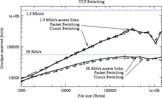
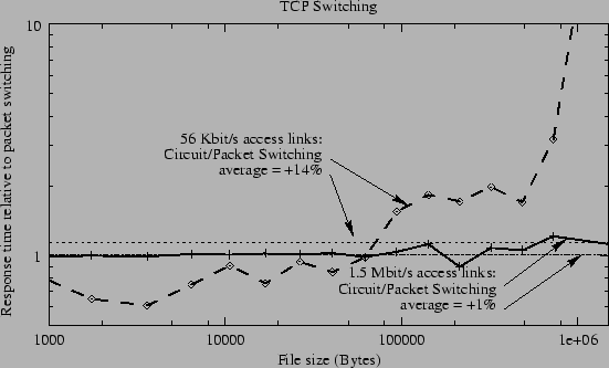
Figures 3.10 and 3.11 show the goodput and the response time, respectively, as a function of the file size. One can see the effects of TCP congestion control algorithms; the shortest flows have a very low goodput. This is mainly due to the slow-start mechanism that begins the connection at a low rate.
The key observation is that packet switching and circuit switching behave very similar, with circuit switching having a slightly worse average response time (14% worse for 56 Kbit/s access links), but the difference becomes smaller, the faster the access link becomes (only 1% worse for 1.5 Mbit/s access links).
|
|
The reason for circuit switching having worse goodput (and thus response time) is that the transmission time of packets along thin circuits in the core increases the RTT, and this reduces the TCP throughput [139]. For example, to transmit a 1500-byte packet over a 56 Kbit/s circuit takes 214 ms (vs. the 8 ms of a 1.5 Mbit/s link), which is comparable to the RTT on most paths in the Internet. Packet switching does not have this problem because packets are transmitted at the rate of the core link (10 Mbit/s or 600 Mbit/s). In the future, as access links increase in capacity, this increase in the RTT will become less relevant, and circuit switching and packet switching will deliver the same response time.
The simulations confirm that, whereas the use of circuit switching in LANs and access networks is undesirable for the end user, users will see little or no difference in terms of response time when using either circuit switching or packet switching in the core.
0.8!
![\includegraphics[]{fig/TCPSwitchingCloud2}](pmf_thesis_img56.png)
|